The Valveworks USA Model FC Series API 6A Gate Valves are full-bore, high-performance valves designed to operate at wellbore and flowline pressures ranging from 3,000 to 5,000 PSI. This lineup offers reliable sealing, reduced turbulent flow, and a high percentage of parts interchangeability for optimal lifecycle management.
Model FC SERIES GATE VALVES
The Valveworks USA Model FC consists of a lineup of gate valves with reliable, proven designs. This model of gate valves offers the user several options depending on the specific application including achieving a positive seal at wellbore/flowline pressures ranging from 3,000 to 5,000 PSI.
Model FC gate valves are full-bore valves. This allows for downhole tools to be passed through the wellhead and reduces turbulent flow. Model FC valves are similar to each other in design with only slight variations across the lineup, offering a high percentage of parts interchangeability, giving you an efficiency-driven advantage in the management and maintenance of your gate valve fleet and providing optimal lifecycle management integrity.
This brochure provides an in-depth look at the details of this series of gate valves and explains the features, benefits, characteristics, dimensional & technical data and other valuable information needed to determine which valve suits your specific application.
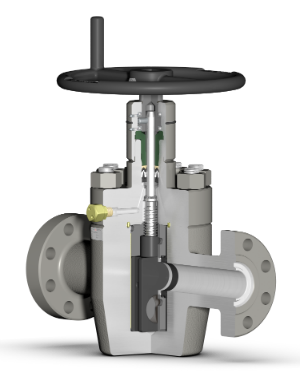
PDF BrochureThe interactive chart below provides a detailed overview of the Valveworks USA Model FC Gate Valve. This full-bore gate valve is engineered for oilfield and flowline applications, with pressure ratings ranging from 3,000 to 5,000 PSI. The labeled diagram illustrates key components and design features, helping operators and engineers assess valve suitability for demanding environments.
Full-Bore Gate Valve – FC Series Labeled Diagram
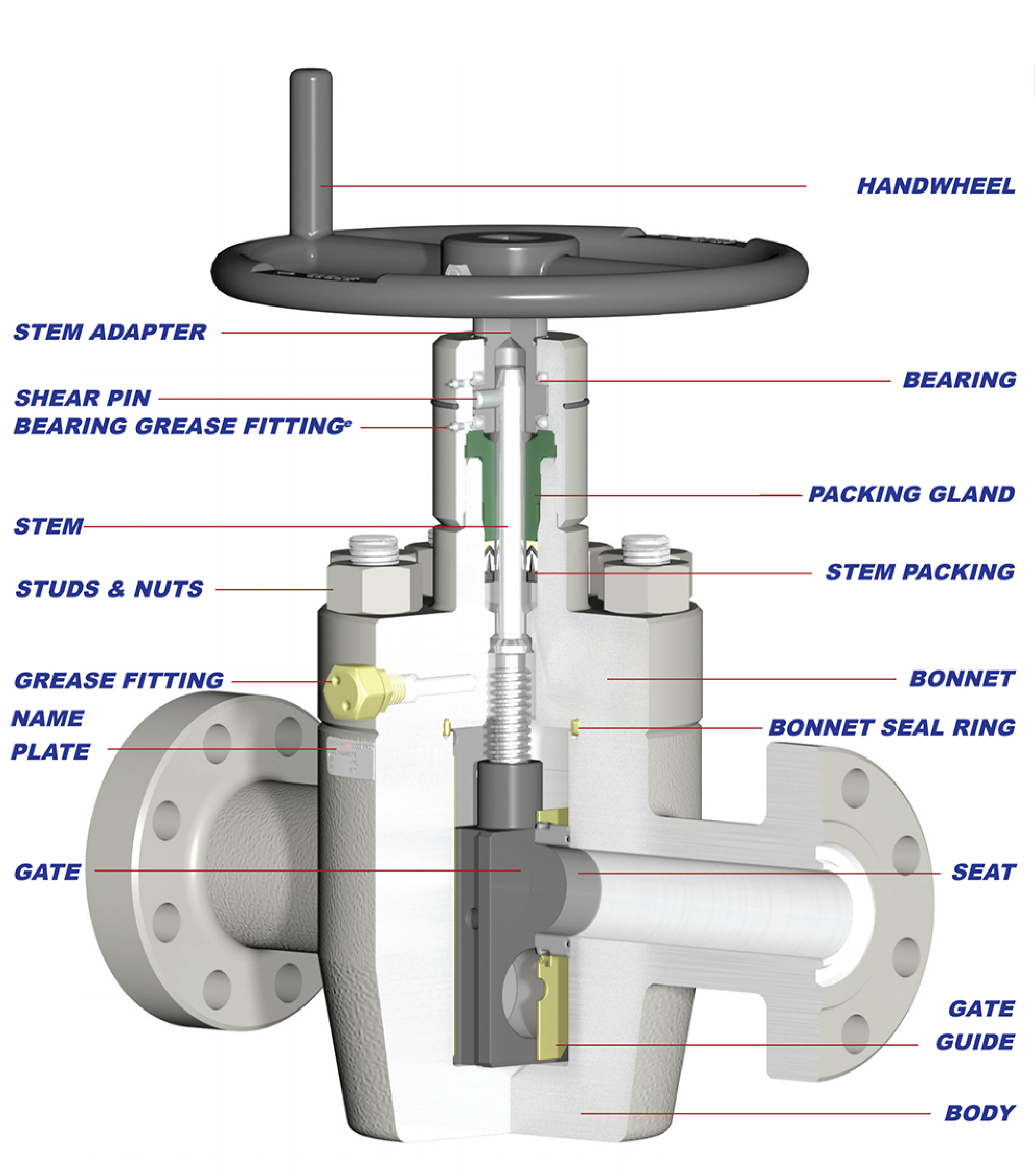
DISCLAIMER: THE ACTUAL PRODUCT MAY VARY SLIGHTLY FROM SHOWN SCHEMATIC DUE TO ENGINEERING APPROVED VARIATION.
WARNING: L7M / B7M STUDS CANNOT BE SUBSTITUED FOR L7 / B7 STUDS
PRODUCT FEATURES
This table outlines the technical specifications of the Valveworks USA FC Series Gate Valve. It includes details on flow direction, bore sizes, pressure ratings, PSL levels, material classes, body configuration, sealing mechanisms, and operational features. The Model FC is a bidirectional, forged-body, slab gate valve designed for through-conduit flow and reliable pressure sealing.
| Key Features | MODEL FC |
|---|---|
| Flow Direction | Bidirectional |
| Available Bore Sizes & Rated Working Pressure (PSI)a,b | 2-1/16” 5K 2-9/16” 5K 3-1/8” 3K / 5K 4-1/16” 3K / 5K |
| Available PSLc | 1, 2, 3, 3G, 4d |
| Material Classes | AA, BB, EE, FF, HH |
| Valve Body | Forged |
| Gate Type | Slab |
| Sealing Action | Pressure-Energized |
| Operation | Manuale |
| Bore Type | Through-Conduitf |
| Gate/Seat Seal | Metal to Metal |
| Stem Type | Non-Rising |
| Stem Packing Type | Opti-Seal |
| Repacking | Yes |
| Thrust Bearing | 2g |
| Body Lubrication Fittings | 1 |
| Body/Bonnet Connection | Bolted |
| End Connections | Flanged (RTJ) |
| Temperature Range | -75°F (-60°C) to 250°F (121°C) |
a. 2 1/16” x 1 13/16”, 3 1/8” x 3 3/16”, 4 1/16” x 4 1/8”, and 4 1/16” x 4 1/4” available upon request.
b. 10/15K available in XPR1 or FC upon request.
c. Product Specification Level
d. PSL 3 & 4 available upon request.
e. Also referred to as “HANDWHEEL OPERATED”
f. Also referred to as “FULL-OPENING”.
g. Valve bonnet equipped with grease ports and fittings for bearing lubrication.
ENGINEERING NOTES
Pressure Testing – FM Series gate valves are not intended to be tested through the body lubrication fittings. These fittings are designed for lubrication purposes only. Shell tests and gate/seat tests shall be conducted from the end/outlet connection by qualified personnel only. Ball Screw Operated (BSOP) – FM Series gate valves are offered with a ball screw operator, which greatly reduces the operating torque when opening and/or closing the valve.TEMPERATURE RATING
The following table defines the temperature classifications for Valveworks USA gate valves, specifying the operating temperature ranges for each classification. These ratings ensure optimal performance in extreme cold and high-temperature industrial applications, making them ideal for oilfield and high-pressure environments.
| Temperature Classification | Operating Temperature Range (°F/°C) |
|---|---|
| K | -75°F (-60°C) to 180°F (82°C) |
| L | -50°F (-46°C) to 180°F (82°C) |
| N | -50°F (-46°C) to 140°F (60°C) |
| P | -20°F (-29°C) to 180°F (82°C) |
| S | 0°F (-18°C) to 140°F (60°C) |
| T | 0°F (-18°C) to 180°F (82°C) |
| U | 0°F (-18°C) to 250°F (121°C) |
| V | 35°F (2°C) to 250°F (121°C) |
MATERIAL REQUIREMENTS
The following table details the API 6A material class requirements for Valveworks USA gate valves, specifying the minimum material composition for body, bonnet, end connections, outlet connections, pressure-controlling parts, and stems. This classification ensures compliance with high-pressure industrial and oilfield standards.
| Material Class | Service Type | Minimum Material Requirements | |
|---|---|---|---|
| Body, Bonnet, End & Outlet Connections | Pressure-Controlling Parts & Stems | ||
| AA | General Service | Carbon or Low-Alloy Steel | Carbon or Low-Alloy Steel |
| BB | General Service | Carbon or Low-Alloy Steel | Stainless Steel |
| CC | General Service | Stainless Steel | Stainless Steel |
| DD | Sour Servicea | Carbon or Low-Alloy Steelb | Carbon or Low-Alloy Steelb |
| EE | Sour Servicea | Carbon or Low-Alloy Steelb | Stainless Steelb |
| FF | Sour Servicea | Stainless Steelb | Stainless Steelb |
| HH | Sour Servicea | Corrosion-Resistant Alloy (CRA)acd | Corrosion-Resistant Alloy (CRA)acd |
VALVEWORKS USA GATE VALVE MODEL EXPLANATION

DIMENSION KEY
The following table defines key dimensional terms used in Valveworks USA gate valve specifications. Each key provides a description of its corresponding measurement or feature, ensuring clarity for engineers and professionals in high-pressure industrial applications.
| Key | Description |
|---|---|
| A | Face to Face |
| B | Valve Bore Size |
| C | Bore Centerline to Bottom |
| D | Bore Centerline to Top |
| E | Handwheel Diameter |
| NT | Number of Turns |
| RJ | Ring Joint |
| BSS | Bonnet Stud Size |
| N | Number of Studs |
| WT | Approximate Weight |
| HT | Handwheel Operating Torque |
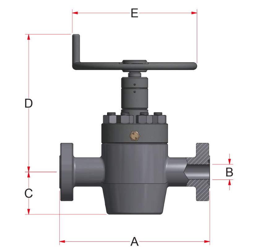
This table provides dimensional specifications for Valveworks USA Model FC Series Gate Valves, detailing working pressure (WP), valve sizes, dimensions (A–E), flange specifications, and performance ratings including weight and operating torque (HT).
| Size (in) | WP (PSI) | Dimensions (inches) | Flange Specifications | Weight (LBS) | HT (FT-LBS) | |||||||
|---|---|---|---|---|---|---|---|---|---|---|---|---|
| A | B | C | D | E | NT | RJ | BSS | N | ||||
| 2-1/16 | 5K | 14 5/8 | 2 1/16 | 5 7/8 | 18 7/8 | 14 | 12 | R-24 | 7/8 | 8 | 189 | 32 |
| 2-9/16 | 5K | 16 5/8 | 2 9/16 | 6 5/16 | 19 1/2 | 16 | 16 1/4 | R-27 | 1 | 8 | 275 | 49 |
| 3-1/8 | 3K | 17 1/8 | 3 1/8 | 7 13/16 | 20 1/2 | 16 | 17 1/2 | R-31 | 1 1/8 | 8 | 337 | 40 |
| 5K | 18 5/8 | 3 1/8 | 7 9/16 | 20 1/2 | 16 | 17 1/2 | R-35 | 1 1/8 | 8 | 355 | 67 | |
| 4-1/16 | 3K | 20 1/8 | 4 1/16 | 9 5/16 | 22 | 20 | 23 1/4 | R-37 | 1 1/4 | 8 | 498 | 550 |
| 5K | 21 5/8 | 4 1/16 | 9 13/16 | 22 | 20 | 23 1/4 | R-39 | 1 1/4 | 8 | 550 | 113 | |
ABBREVIATION KEY
- FC = Model VW-FC
- HWO = HANDWHEEL OPERATED (MANUAL)
- SG = SLAB GATE
- FE = FLANGED END
- RTJ = RING TYPE JOINT
- PSL = PRODUCT SPECIFICATION LEVEL
- PR = PERFORMANCE REQUIREMENT
- CRA = CORROSION-RESISTANT ALLOY
- XYL = XYLAN®
- NIT = NITRIDE