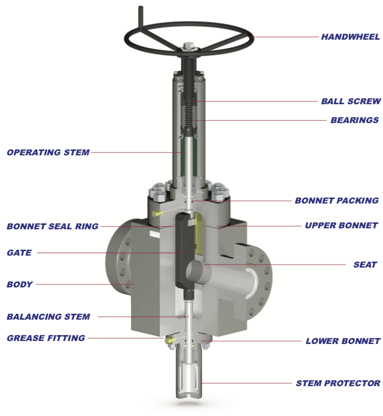
FM SERIES GATE VALVES
The Valveworks USA FM Series consists of a lineup of gate valves with reliable, proven designs where a 4 1/16”, 5 1/8”, 7 1/16” bore is required. This series of gate valves offers the user several options depending on the specific application.
FM Series gate valves are full bore, through conduit valves. This allows for downhole tools to be passed through the wellhead and / or Christmas tree and reduces turbulent flow. FM Series valves are similar to each other in design with only slight variations across the lineup, offering a high percentage of parts interchangeability, giving you an efficiency-driven advantage in the management and maintenance of your gate valve fleet, and providing optimal life cycle management integrity.
This brochure provides an in-depth look at the details of this series of gate valves and explains the features, benefits, characteristics, dimensional & technical data, and other valuable information needed to determine which valve provides an optimal solution for your specific application.
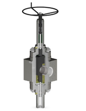
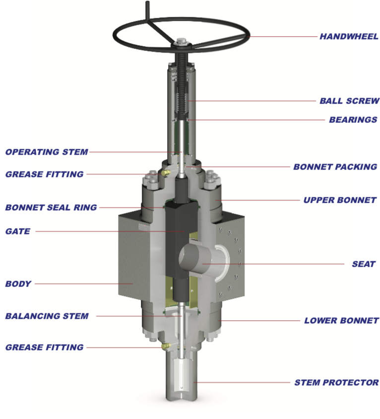
MODEL FM1- BIDIRECTIONAL, SLAB GATE, STUDDED BODY
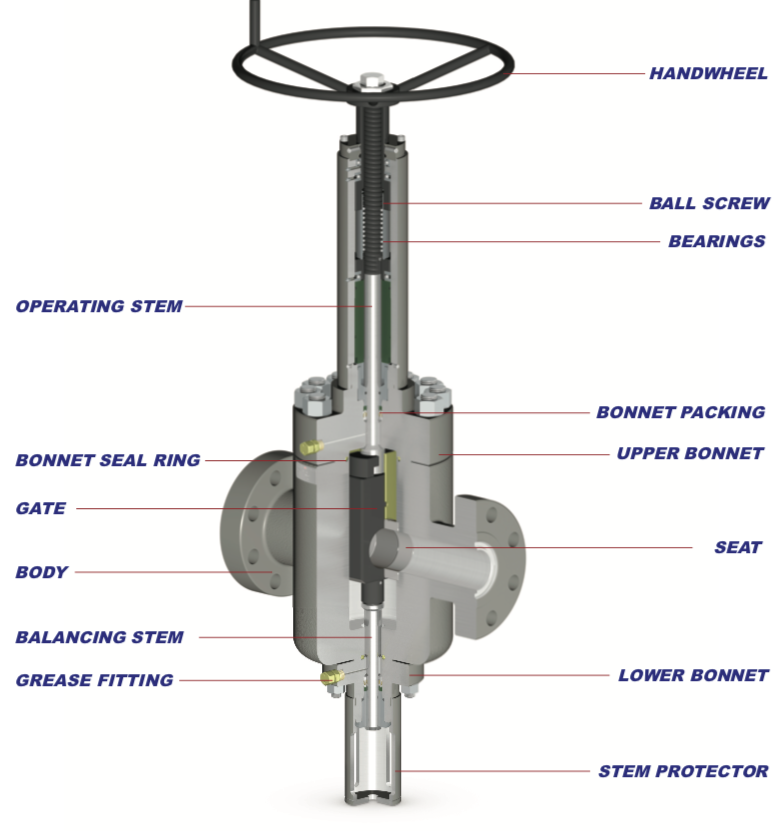
MODEL FM2 – BIDIRECTIONAL, SLAB GATE, FLANGED BODY
MODEL FM3 10K – UNIDIRECTIONAL, SLAB GATE, FLANGED BODY
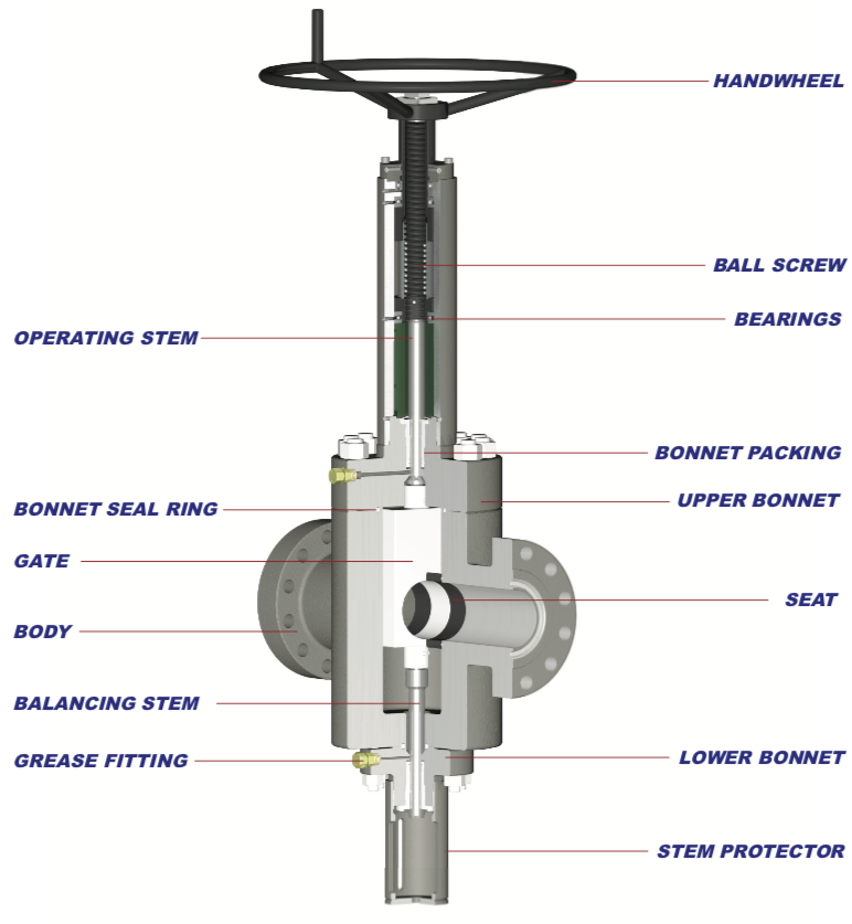
MODEL FM3 15K- BIDIRECTIONAL, SLAB GATE, FLANGED BODY
DISCLAIMER: THE ACTUAL PRODUCT MAY VARY SLIGHTLY FROM SHOWN SCHEMATIC DUE TO ENGINEERING APPROVED VARIATION.
WARNING: L7M / B7M STUDS CANNOT BE SUBSTITUED FOR L7 / B7 STUDS
TABLE 1 – PRODUCT FEATURES
| FEATURES | Model FM1 | Model FM2 | Model FM3 |
|---|---|---|---|
| Flow Direction | Bidirectional | Bidirectional | Bidirectional |
| Available Bore Sizes & Rated Working Pressure (PSI)b | 7-1/16” 10M, 7-1/16” 15M | 4-1/16” 15M | 5-1/8” 10M, 5-1/8” 15M |
| Available PSLa | 1,2,3,3G,4 | 1,2,3,3G,4 | 1,2,3,3G,4 |
| Material Classes | EE, FF, HH | EE, FF, HH | EE, FF, HH |
| Valve Body | FORGED | FORGED | FORGED |
| Gate Type | SLAB | SLAB | SLAB |
| Sealing Action | PRESSURE ENERGIZED | PRESSURE ENERGIZED | PRESSURE ENERGIZED |
| Operation | Manualb | Manualb | Manualb |
| Bore Type | Thru-Conduitc | Thru-Conduitc | Thru-Conduitc |
| Gate/Seat Seal | Metal to Metal | Metal to Metal | Metal to Metal |
| Stem Type | Rising | Rising | Rising |
| Stem Packing Type | Opti-Seal | Opti-Seal | Opti-Seal |
| Repacking | Yesd | Yesd | Yesd |
| Bearing | 3 | 3 | 3 |
| Body Lubrication Fittings | 2e | 2e | 2e |
| Body/Bonnet Connection | Bolted | Bolted | Bolted |
| Balance Stem | Yes | Yes | Yes |
| End Connections | Flanged (RTJ) or Studded | Flanged (RTJ) | Flanged (RTJ) |
| Temperature Range | -75°F (-60°C) Thru 250°F (121°C) | -75°F (-60°C) Thru 250°F (121°C) | -75°F (-60°C) Thru 250°F (121°C) |
a. Product Specification Level
b. Ball Screw Operated (BSOP) – Manual gate valve with torque reduction operator. See engineering note titled “Ball Screw Operated (BSOP)” for details.
c. Also referred to as “FULL OPENING”
d. Repacking is achieved via stem backseat method.
e. Ball screw housing equipped with grease port(s) and fitting(s) for bearing lubrication.
ENGINEERING NOTES
Pressure Testing – FM Series gate valves are not intended to be tested through the body lubrication fittings. These fittings are designed for lubrication purposes only. Shell tests and gate/seat tests shall be conducted from the end/outlet connection by qualified personnel only.
Ball Screw Operated (BSOP) – FM Series gate valves are offered with a ball screw operator, which greatly reduces the operating torque when opening and / or closing the valve.
TABLE 2 – TEMPERATURE RATING
| TEMPERATURE CLASSIFICATION | OPERATING RANGE |
|---|---|
| K | -75°F (-60°C) TO 180°F (82°C) |
| L | -50°F (-46°C) TO 180°F (82°C) |
| N | -50°F (-46°C) TO 140°F (60°C) |
| P | -20°F (-29°C) TO 180°F (82°C) |
| S | 0°F (-18°C) TO 140°F (60°C) |
| T | 0°F (-18°C) TO 180°F (82°C) |
| U | 0°F (-18°C) TO 250°F (121°C) |
| V | 35°F (2°C) TO 250°F (121°C) |
TABLE 3 – MATERIAL REQUIREMENTS
| MATERIAL CLASS | MINIMUM MATERIAL REQUIREMENTS | ||
|---|---|---|---|
| BODY, BONNET END & OUTLET CONNECTIONS | PRESSURE-CONTROLLING PARTS & STEMS | ||
| AA | General Service | Carbon or Low-Alloy Steel | Carbon or Low-Alloy Steel |
| BB | General Service | Carbon or Low-Alloy Steel | Stainless Steel |
| CC | General Service | Stainless Steel | Stainless Steel |
| DD | Sour Servicea | Carbon or Low-Alloy Steelb | Carbon or Low-Alloy Steelb |
| EE | Sour Servicea | Carbon or Low-Alloy Steelb | Stainless Steelb |
| FF | Sour Servicea | Stainless Steelb | Stainless Steelb |
| HH | Sour Servicea | CRAacd | CRAacd |
VALVEWORKS USA DESCRIPTION KEY
| Specification | GV, 6A |
|---|---|
| Valveworks USA Model | MOD MDS |
| Gate Type | EXP GATE |
| Bore Size (Nominal) | 2-1/16" |
| Rated Working Pressure | 5M |
| End Connection | FE |
| Material Class | DD-NL |
| Temperature Rating/Classification | KU |
| PSL | 1- |
| PR | 2 |
| Operation Type | HWO |
ABBREVIATION KEY
- BSOP = BALL-SCREW OPERATED
- SG = SLAB GATE
- FE = FLANGED END
- STD =STUDDED END
- RTJ = RING TYPE JOINT
- D/O = DIRECT OPERATING
- R/A = REVERSE ACTING
- KU = TEMP. CLASS K/U (-75°F TO 250°F)
- LU = TEMP. CLASS L/U (-50°F TO 250°F)
- PU = TEMP. CLASS P/U (-20°F TO 250°F)
- PSL = PRODUCT SPECIFICATION LEVEL
- PR = PERFORMANCE REQUIREMENT
- CRA = CORROSION-RESISTANT ALLOY
- HF = HARDFACED TUGSTON CARBIDE
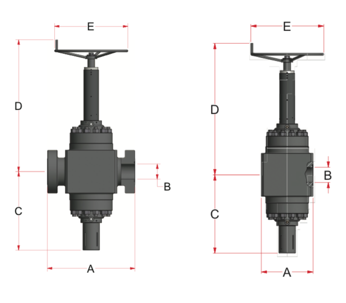
DIMENSION TABLE KEY
| Key | Description |
|---|---|
| A | End to End |
| B | Valve Bore Size |
| C | Bore Centerline to Bottom |
| D | Bore Centerline to Top |
| E | Handwheel Diameter |
| NT | Number of Turns |
| RJ | Ring Joint |
| BSS | Bonnet Stud Size |
| WT | Approximate Weight |
FLANGED GATE VALVES
| SIZE | WP (PSI) | A | B | C | D | E | NT | RJ | BSS | WT (LBS) |
|---|---|---|---|---|---|---|---|---|---|---|
| 4 1/16 | 15K | 29 | 4 1/16 | 26 | 54 1/4 | 28 | 9 5/8 | BX-155 | 1 | 2050 |
| 5 1/8 | 10K | 29 | 5 1/18 | 26 | 52 1/8 | 28 | 11 3/4 | BX-169 | 1 3/8 | 1331 |
| 5 1/8 | 15K | 35 | 5 1/18 | 28 1/8 | 56 1/4 | 34 | 13 | BX-169 | 1 3/4 | 2331 |
| 7 1/16 | 10K | 35 | 7 1/16 | 36 1/2 | 61 1/4 | 34 | 17 3/4 | BX-156 | 1 3/4 | 4420 |
| 7 1/16 | 15K | 40 5/8 | 7 1/16 | 36 1/2 | 61 1/4 | 34 | 17 3/4 | BX-156 | 2 | 5410 |
STUDDED GATE VALVES
| SIZE | WP(PSI) | A | B | C | D | E | NT | RJ | BSS | WT(LBS) |
|---|---|---|---|---|---|---|---|---|---|---|
| 7 1/16 | 10K | 24 | 7 1/16 | 36 1/2 | 61 1/4 | 34 | 17 3/4 | BX-156 | 1 3/4 | 4630 |
| 7 1/16 | 15K | 24 | 7 1/16 | 36 1/2 | 61 1/4 | 34 | 17 3/4 | BX-156 | 2 | 4690 |